• No products in the cart.
Checkout

BlinkTech

Latest News

IR Camera used for Fire Protection in Wood Pellet Storage

By Comments Off on IR Camera used for Fire Protection in Wood Pellet Storage

FIRE-SCAN monitoring system in pellet production

Wood pellets as an alternative and high-quality fuel have become increasingly important in recent years. Their local origin from sustainable cultivation in the region has given WUN Bioenergie GmbH the opportunity to respond to market demand as an environmentally friendly supplier of raw materials. However, like other fuels, stored wood pellets need to be secured and monitored around the clock to prevent causes of devastating damage in the event of a fire, for example. Robust and reliable thermography solutions are a suitable tool for plant protection here.

At its Wunsiedel site, WUN Bioenergie GmbH has more than one string to its bow. Among other things, it operates a biomass cogeneration plant there. Treetop wood with a high proportion of conifer needles and twig residues are used as heating fuel, as these are cheap and environmentally friendly to procure. The water content amounts to about 30 – 60 percent, which does not pose any problems for the operation of a highly efficient ORC (Organic Rankine Cycle) plant.

Fire protection with FIRE-SCAN

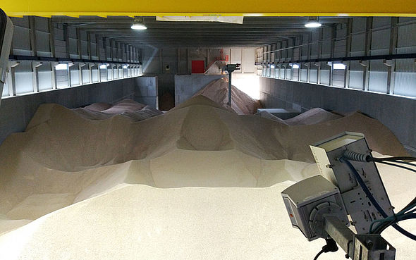
Wood pellets are a high-quality and energy-rich fuel. For this reason, the storage facilities must be monitored around the clock in the interest of fire protection. This is made possible by high-quality thermographic systems that simultaneously track the moisture content of the pellets during the drying process with high thermographic and geometric resolution. The real-time evaluation of the thermal images allows an accurate assessment of this process.


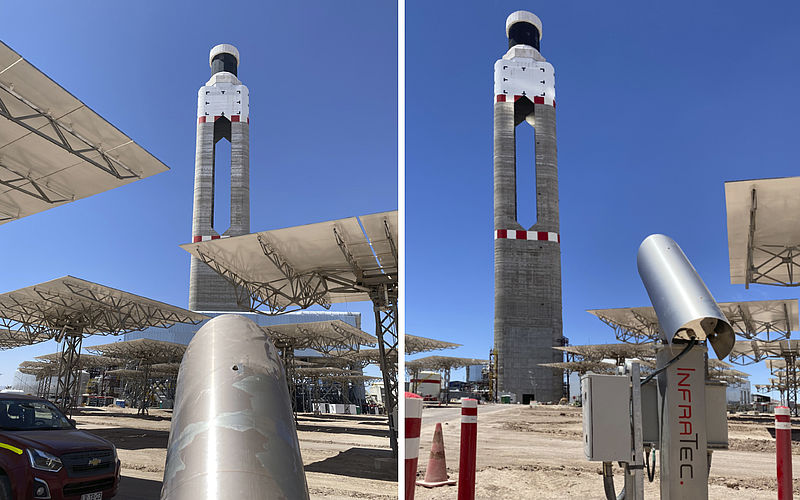
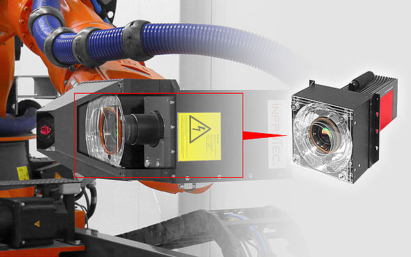
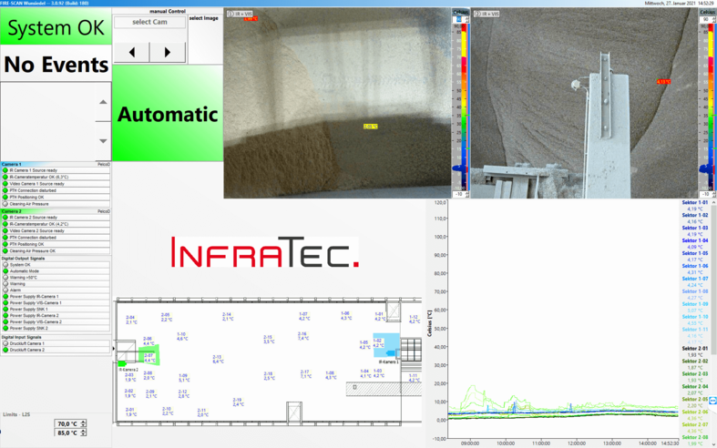
Fig. 1: The heart of the FIRE-SCAN hardware, well protected and equipped for continuous use

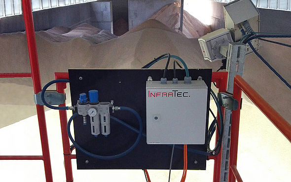
The FIRE-SCAN fire monitoring system from InfraTec is used in the WUN Bioenergie warehouse. This thermography automation solution is equipped with VarioCAM® HDx head infrared cameras and designed for a 24/7 continuous operation. The very stable and highly accurate digital infrared cameras of the VarioCAM® HDx head series from InfraTec are based on thermally and geometrically high-resolution microbolometer FPA detectors with (640 × 480) IR pixels and provide brilliant 16-bit thermal images in real time.

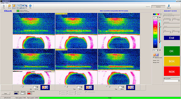
In addition to automated continuous monitoring, the associated software also allows manual interactions by the operating personnel. The surface temperatures measured by the cameras ensure constant quality monitoring of the pellets, as the FIRE-SCAN software monitors another threshold temperature in addition to the threshold values for early fire detection. This allows conclusions to be drawn about the moisture content of the pellets. Thus, the crane operator can actively ensure that the drying process runs smoothly. If the system detects a heat nest at up to 40 °C, the pellets are rearranged by the crane system. At 60 °C, they are removed from storage and, in the event of a fire, extinguished with quartz sand if necessary.


Download Case Study        Variocam HDx

High Speed Video – Combustion Studies

By Comments Off on High Speed Video – Combustion Studies

Combustion research involves the complex study of a chemical reaction between multiple substances. The speed at which the substances combine is very high due to the energy that is generated by the combination of oxygen and heat or flame. The study of combustion is based on the knowledge of chemistry, physics, and mechanics. Combustion research is utilized in a wide range of applications, including engine testing in the automotive industry and in rocket and jet engine testing in the aerospace industry.

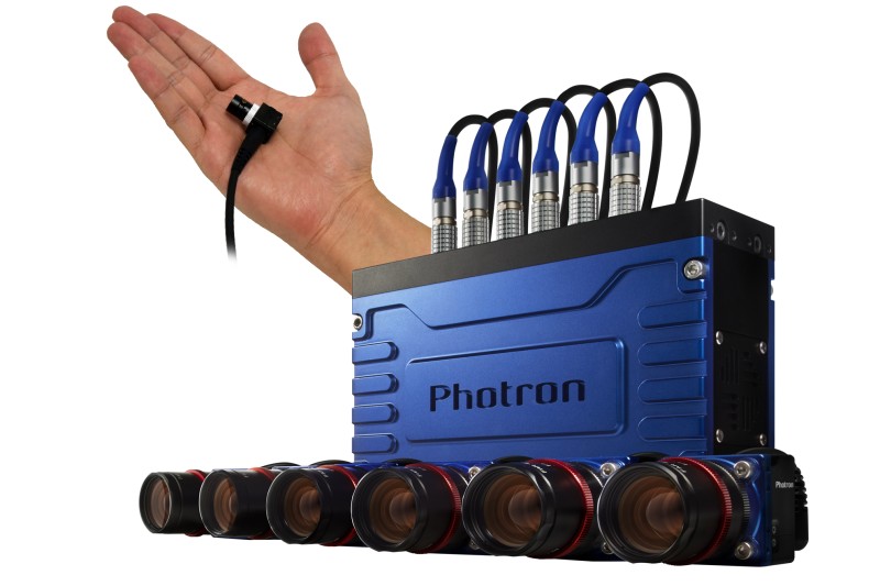
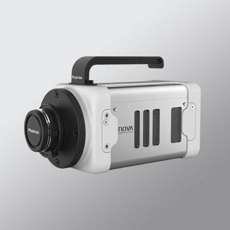
Photron cameras are often used in combustion studies due to their light sensitivity and PFV software which adds a number of features that prove helpful in those studies.

Academic Paper – Study of stratified lean premixed methane/air low-swirl turbulent flame

Simultaneous high-repetition rate (3 kHz) CH2O planar laser-induced fluorescence (PLIF) and particle image velocimetry (PIV) measurements were performed in in turbulent low swirl stratified premixed methane/air flames to investigate the large-scale spatial and temporal evolution of the flame and flow dynamics. In addition, PLIF of OH and CH2O at a low-repetition rate (10Hz) were carried to study the global effect of equivalence ratio, ϕ, on the flame. A low swirler burner was used to stabilize a wide range of flames, from close-to-quenching lean flames to close to stoichiometric flame with ϕ = 0.9. The flames exhibit a laminar flamelet structure in the leading front and thickened flame structure with local quenching at the trailing edge. Detailed statistical data are obtained, including the velocity field, the mean flame location; preheat layer thickness, flame brush thickness and the flame surface density. These data provide a useful database for comparison of combustion model simulations. The results reveal interesting flame behaviour; depending on the equivalence ratio the large scale interaction between the flame and the flow field takes different forms.

View Paper

Video Examples – Blue Combustion

High Speed IR Camera Mining

By Comments Off on High Speed IR Camera Mining

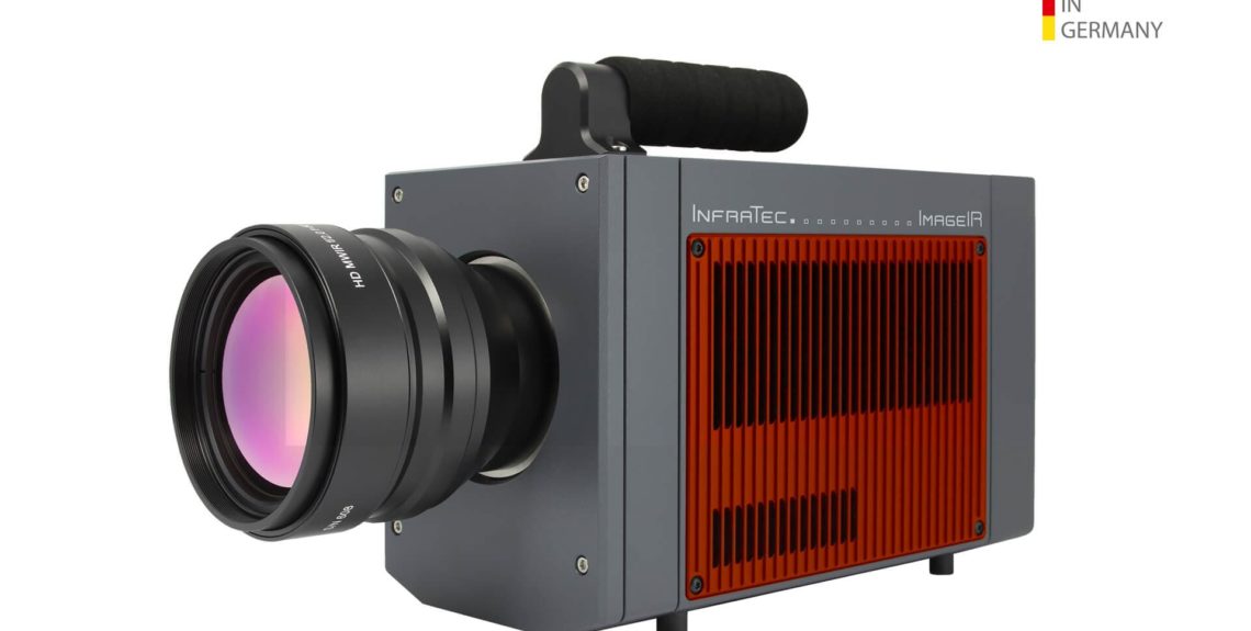
High Speed IR capabilities can be used across a number of sectors including for blast monitoring. The ImageIR® 8300 hs with its features is a masterpiece of precision:

View Product Information


Detection of Smallest Details
The geometric resolution of (640 x 512) IR pixels ensures a brilliant image of the measured objects down to the smallest detail
Precise Measurement at Top Speed
With a frame rate of 1,004 Hz in full-frame mode, even extremely fast moving objects and highly dynamic thermal processes are detected
Identification of the Smallest Temperature Differences
With better than 20 mK the camera achieves an impressively high thermographic resolution
Short Integration Times and Extremely High Frame Rates
Large detector pixels (pixel pitch 25 µm) ensure particularly high detector sensitivity for the shortest integration times at extremely high frame rates
Longer Cooler Lifetime
Innovative HOT Long Life Technology extends cooler lifetime through higher working temperature and reduced cooling load
Digital High-speed Data Acquisition
Superfast industrial grade 10 GigE interface makes the thermographic images in real time available on your computer

To find out more on this technology we will be looking to hold a virtual demonstration with some pre recorded data. Please register your interest below and we will contact you when dates are finalised.


AOS High Speed Camera – Crash Test

By Comments Off on AOS High Speed Camera – Crash Test

From minor paint damage to fatal road accidents: Every year, numerous damage reports reach the insurance companies. In order to investigate accidents and their consequences and to act preventively, a leading Swiss insurance company carries out its own accident research. AOS is a perfect choice for the high-speed recordings and with the performance and quality of their range of cameras.

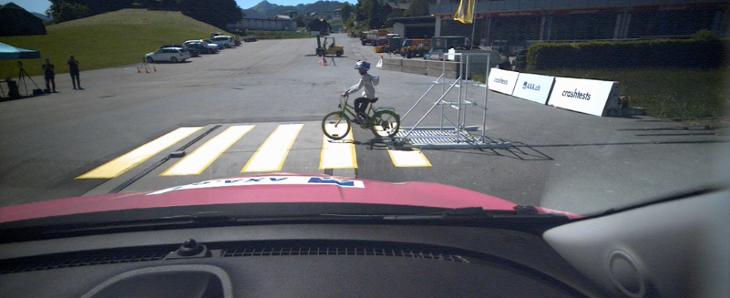
In a collision test of a car with a child’s bike, the M-VIT in combination with ALED 2500 LED illumination system delivered excellent results.

Bicycle Crash M-VIT 2000fps onboard – Accident research from AOS Technologies AG


View M-VIT High Speed Camera.
View Lighting Solution

Additive Manufacturing Thermal Camera use

By Comments Off on Additive Manufacturing Thermal Camera use

Temperature is one of the key factors the quality of the process and thereby also the quality of the final product depends on. Thermographic cameras can for example be integrated directly into a laser sintering machine. They allow users to measure various temperature related process parameters.

Most relevant are the detection of the temperature distribution of the powder bed surface and the measurement of the melting temperature. Both can be realised while the laser is in operation (in-situ measurement) and for temperature ranges more than 2,000 °C.


Download PDF View Product

Case Study: Monitoring the Surface Temperature on Curing Epoxy Resin Samples

By Comments Off on Case Study: Monitoring the Surface Temperature on Curing Epoxy Resin Samples

Epoxy resin systems are mostly used as a matrix material in fibre composites. In a variety of manufacturing processes, the corresponding resin system is processed in a flowable state. The material only acquires its rigidity in a subsequent curing process. This is characterized by an exothermic chemical reaction with a pronounced temperature dependence.

During the curing process, a polymer with a strongly cross‐linked structure – also called a thermoset – is formed. Polymers generally have low thermal conductivity. Particularly in the case of thick‐walled components, these properties lead to an inhomogeneous temperature distribution with hotspots. This entails the risk that the material properties of the polymers deteriorate, for example, their strength decreases, porosity increases, or they even ignite. In addition, the cross‐linking curing reaction of epoxy resins is accompanied by a volumetric shrinkage of the material. This can sometimes cause strong mechanical residual stresses in the material, which can lead to the failure of the component before the actual loading. A precise numerical prediction of the temperature development in components is essential in order to develop suitable temperature controls in the manufacturing process of fibre composite components.

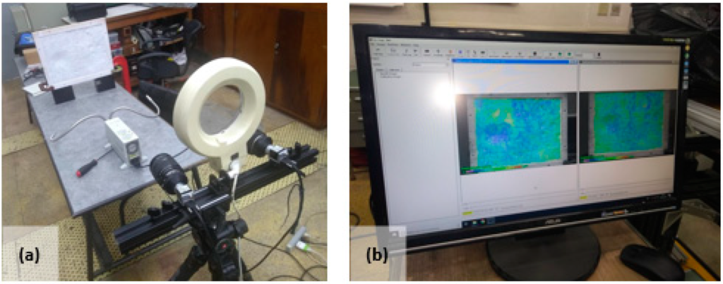
The Institute of Applied Mechanics of Clausthal University of Technology develops mathematical models based on a wide range of experimental studies. These material models reflect the mechanical, thermal, and in this case, the chemical behaviour of the polymer. Implemented in finite element software, they enable the prediction of the process or component behaviour. Against the background of the aforementioned challenges to process control in the production of fibre composite components, Dipl.‐Ing. Chris Leistner and his colleagues at the Institute of Applied Mechanics, among other topics, examined the pure epoxy resin system as part of their tests. They use temperature measurements on epoxy resin samples during curing in order to validate the model.

Download Case Study

*Case Study Provided from Infratec EU in conjunction with Clausthal University of Technology Institute of Applied Mechanics

Use of High-speed Thermography in Laser High-temperature Capillary Gap Brazing

By Comments Off on Use of High-speed Thermography in Laser High-temperature Capillary Gap Brazing

Lasers are extremely versatile tools in industry and manufacturing technology. Due to their flexibility, they serve as a key technology for implementing the goals of industry 4.0. Although laser cutting and welding are nowadays regarded as turnkey technologies, the majority of laser applications, for example joining of hybrid materials, 3D printing or ultra-short pulse processing, still require considerable research and development.

The Laser Application Center (LAC) of Aalen University intensively researches and develops new methods of laser material processing. Thus, innovative materials for Additive Manufacturing are developed and investigated within public R&D projects, including magnetic materials or electrical energy storage materials for electromobility. Another focus is lightweight construction. Here, among other things, mixed metallic compounds and hybrid lightweight structures made of aluminium and CFRP for CO2-efficient mobility concepts are investigated. The newly developed processes aluminium laser polishing and high-temperature capillary gap brazing are already being used in industrial projects.

View Case Study ImageIR


A-LED 2500, more light than ever

By Comments Off on A-LED 2500, more light than ever

Lighting is such an important part of gathering useful data from your high speed tests. Having a high powered, flicker free LED light  is probably the next most important tool to the camera itself.

The new AOS A-LED 2500 high power LED system with up to 4 miniaturized heads, with 150 Watts each comes now with higher efficiency electronics getting even more light out. For all connected LED heads the controller does have overheating alerts and short circuit protection. A-LED 2500 is ready for constant or strobing illumination synchronized to most brands of high speed cameras.

The system is High-g crash proof up to 100g /11msec. It comes with a charger and all necessary cables.

Paired with the AOS M-Vit (or any of their high G range), this light source is perfect for crash test applications

Cleaning the Sensor on your High Speed Camera

By Comments Off on Cleaning the Sensor on your High Speed Camera

Keeping your camera sensor clean and free of debris is very important to obtaining the best images possible. If you notice smudges or other spots showing up on the image it’s possible the sensor may need to be cleaned. The tech tip will go over four methods we use here in our lab for cleaning our sensors when needed. We recommend performing the cleaning steps that remove the smudge/dirt in the least invasive way possible.

1) The first method is to use a dust removal tool such as the one pictured aside. The lens mount can be kept on for this method and simply point the tool at the sensor and give it a few good squeezes of air. If the dust/dirt still is present then move onto the next method.

These ear syringes can be purchased from most chemists and typically cost less than $10


2) The second method involves using compressed air. Always ensure you are using clean compressed air and that you do not point the air directly at the sensor but shoot air at it from the sides. For this method and the two that come after the lens mount will need to be removed. Remove the four black screws holding in the mount and then apply the compressed air from the side of the camera as pictured below.

Compressed air can be purchased from Jaycar or similar hardware stores.


3) If compressed air hasn’t removed the debris or you are dealing with a smudge on the sensor then you will have to use a lens cloth to take care of the issues. Select a high quality disposable lens cloth and ensure you use a new cloth each time you clean a sensor. With the lens mount removed, use a single quick motion across the affected area and make sure to never re-use a portion of the cloth that has already touched the sensor.

4) The last method used if none of the other methods have been successful is using isopropyl alcohol and then wiping the sensor again with a lens cloth. Please ensure to use the highest purity isopropyl alcohol while using the same single quick motion wiping method across the affected area with a lens cloth.

*Elecrtro-static Discharge  events may cause damage to the image sensor. Take extreme care when cleaning the image sensor surface

  • Always take appropriate anti-static precautions when cleaning or working near the image sensor
  • Do not use any form of cleaning equipment using electrostatic or “charged fiber” technology
  • Always discharge electrostatic discharge build up in your body by touching a grounded metallic surface before working on a camera
  • Very gently, use only clean and dry air to remove dust
  • For stubborn contamination use high grade pure IPA with optical wipes of ‘clean room’ grade
  • wipe across the sensor in a single action, to not rub to avoid abrasive damage.


*Tech Tip originally created by Photron USA, see all their tech tips here