• No products in the cart.
Checkout

BlinkTech

News

Use of High-speed Thermography in Laser High-temperature Capillary Gap Brazing

By Comments Off on Use of High-speed Thermography in Laser High-temperature Capillary Gap Brazing

Lasers are extremely versatile tools in industry and manufacturing technology. Due to their flexibility, they serve as a key technology for implementing the goals of industry 4.0. Although laser cutting and welding are nowadays regarded as turnkey technologies, the majority of laser applications, for example joining of hybrid materials, 3D printing or ultra-short pulse processing, still require considerable research and development.

The Laser Application Center (LAC) of Aalen University intensively researches and develops new methods of laser material processing. Thus, innovative materials for Additive Manufacturing are developed and investigated within public R&D projects, including magnetic materials or electrical energy storage materials for electromobility. Another focus is lightweight construction. Here, among other things, mixed metallic compounds and hybrid lightweight structures made of aluminium and CFRP for CO2-efficient mobility concepts are investigated. The newly developed processes aluminium laser polishing and high-temperature capillary gap brazing are already being used in industrial projects.

View Case Study ImageIR


A-LED 2500, more light than ever

By Comments Off on A-LED 2500, more light than ever

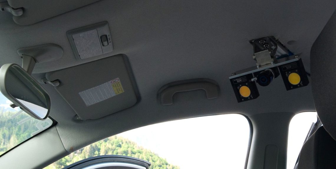
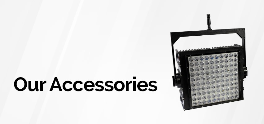
Lighting is such an important part of gathering useful data from your high speed tests. Having a high powered, flicker free LED light  is probably the next most important tool to the camera itself.

The new AOS A-LED 2500 high power LED system with up to 4 miniaturized heads, with 150 Watts each comes now with higher efficiency electronics getting even more light out. For all connected LED heads the controller does have overheating alerts and short circuit protection. A-LED 2500 is ready for constant or strobing illumination synchronized to most brands of high speed cameras.

The system is High-g crash proof up to 100g /11msec. It comes with a charger and all necessary cables.

Paired with the AOS M-Vit (or any of their high G range), this light source is perfect for crash test applications

Cleaning the Sensor on your High Speed Camera

By Comments Off on Cleaning the Sensor on your High Speed Camera

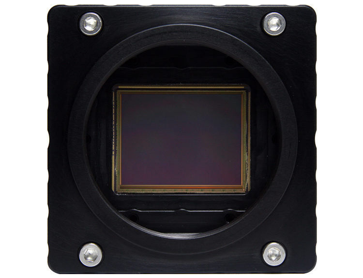
Keeping your camera sensor clean and free of debris is very important to obtaining the best images possible. If you notice smudges or other spots showing up on the image it’s possible the sensor may need to be cleaned. The tech tip will go over four methods we use here in our lab for cleaning our sensors when needed. We recommend performing the cleaning steps that remove the smudge/dirt in the least invasive way possible.

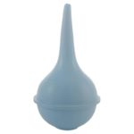
1) The first method is to use a dust removal tool such as the one pictured aside. The lens mount can be kept on for this method and simply point the tool at the sensor and give it a few good squeezes of air. If the dust/dirt still is present then move onto the next method.

These ear syringes can be purchased from most chemists and typically cost less than $10


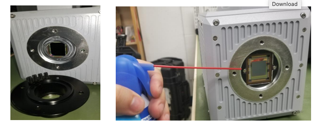
2) The second method involves using compressed air. Always ensure you are using clean compressed air and that you do not point the air directly at the sensor but shoot air at it from the sides. For this method and the two that come after the lens mount will need to be removed. Remove the four black screws holding in the mount and then apply the compressed air from the side of the camera as pictured below.

Compressed air can be purchased from Jaycar or similar hardware stores.


3) If compressed air hasn’t removed the debris or you are dealing with a smudge on the sensor then you will have to use a lens cloth to take care of the issues. Select a high quality disposable lens cloth and ensure you use a new cloth each time you clean a sensor. With the lens mount removed, use a single quick motion across the affected area and make sure to never re-use a portion of the cloth that has already touched the sensor.

4) The last method used if none of the other methods have been successful is using isopropyl alcohol and then wiping the sensor again with a lens cloth. Please ensure to use the highest purity isopropyl alcohol while using the same single quick motion wiping method across the affected area with a lens cloth.

*Elecrtro-static Discharge  events may cause damage to the image sensor. Take extreme care when cleaning the image sensor surface

  • Always take appropriate anti-static precautions when cleaning or working near the image sensor
  • Do not use any form of cleaning equipment using electrostatic or “charged fiber” technology
  • Always discharge electrostatic discharge build up in your body by touching a grounded metallic surface before working on a camera
  • Very gently, use only clean and dry air to remove dust
  • For stubborn contamination use high grade pure IPA with optical wipes of ‘clean room’ grade
  • wipe across the sensor in a single action, to not rub to avoid abrasive damage.


*Tech Tip originally created by Photron USA, see all their tech tips here

Infrared Camera in Electronics and Electrical Engineering

By Comments Off on Infrared Camera in Electronics and Electrical Engineering

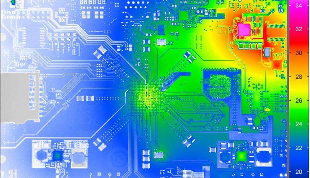
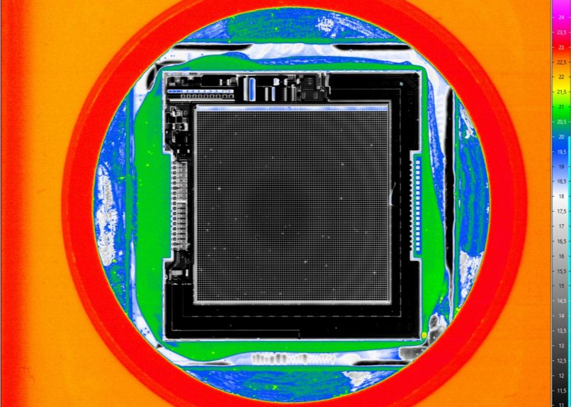
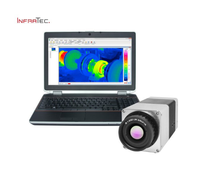
The use of infrared thermography in electronics and electrical industry allows contactless measurement of surface temperatures with an infrared camera without contacting temperature sensors. It is an elegant, non-invasive optical temperature measurement method for simultaneous and temporally high-resolution detection of a number of measurement points.


Infrared Camera Enables Contactless Measurement in Electronics

The thermographic inspection of electronic components and assemblies is an established test procedure for failure detection and quality management – from the development of first prototypes to serial production. This enables, for example, the following to be detected:

  • Hotspots and atypical temperature distributions on the surface of printed circuit boards, integrated circuits and multichip modules
  • Increased contact resistances
  • Increased resistance due to constriction of wires
  • Hidden cracks in joints
  • Power losses due to RF mismatch
  • Incorrect thermal connections of heat sinks
  • Short circuits, soldering defects such as cold solder joints

Thermographic analysis during each development step provides important conclusions for the optimisation of heat management and the design of complex electronic assemblies. In electronics production thermographic temperature measurement is used as a versatile instrument for quality assurance. High-performance thermography has become indispensable for setting critical technological parameters and their permanent monitoring as well as for inline testing of products in the production process and their final functional test.

Download Brochure

IR Based Fever Detection

By Comments Off on IR Based Fever Detection

Major travel hubs like airports, seaports, railway stations and long-distance bus stations are one of the points on which the security measures of public authorities are aimed when infectious diseases such as Coronavirus (2019-nCoV), Severe Acute Respiratory Syndrome (SARS), Ebola Virus Disease (EVD) or Middle East Respiratory Syndrome Coro-navirus (MERS-CoV) cause global problems. From there, diseases can be effectively prevented from spreading further. InfraTec infrared cameras can be used for a corresponding thermal fever screening for passengers. Our thermographic systems enable a non-contact and areal coverage of the body temperature, which preferably is detected at the inner angle of the eye. Slightest differences and thus abnormal body tempera- tures can be displayed and will result in alarms. Performing such health screenings, e.g. via implementing temperature checkpoints, enable the acquisition of important informa- tion as a basis for decision-making for subsequent medical examinations of the selected people and thus serve to secure public areas.

Advantages of using infrared cameras for thermal fever scanning of passengers

  • Contactless and planar temperature measurement without external reference radiator
  • Large field of view for rapid checking of large groups of people
  • Resolution also of smaller areas of the skin (angle of the eye) from a safe distance
  • Display and evaluation in real time
  • Reliable temperature measurements based on low noise infrared detectors and precision calibration
  • Alarming at surpassing temperature thresholds (fever)
  • Easily installable all-in-one unit for continuous monitoring of persons and groups of people
Download Information Sheet View Product Range

Simultaneous Mapping of Wide Temperature Ranges

By Comments Off on Simultaneous Mapping of Wide Temperature Ranges

If you want to measure temperatures in a very wide range with an infrared camera, you normally do this in stages. The neutral density filters are changed gradually from time to time. Adjusted to a specific temperature range, they prevent high-intensity infrared radiation from striking the camera detector and falsifying the measurement result by depolarising the detector pixels. The new High Dynamic Range (HDR) function of the Infrared ImageIR® camera series from InfraTec eliminates the need for such interruptions. It enables measurement scenarios with extremely different temperatures to be recorded continuously.

Capture temperature ranges of over 1,500 K in one image thanks to six positions
The starting point of the HDR function is a fast rotating filter wheel. Designed for such tasks, it rotates at more than 5,000 revolutions per minute. The wheel provides up to six positions ensuring maximum flexibility for demanding measurement tasks. When recording in HDR mode, multiple thermograms with different integration times and different filters are recorded quickly in succession and compiled into an overall image with a high dynamic range.

To activate the HDR function, it is sufficient to select a previously defined calibration range. After that, the rotation of the rotating filter wheel and the composition of the thermogram starts automatically. The measuring range can span up to 1,500 K. In the case of the ImageIR® 8300 hp, this setting can be used to capture full-frame images with (640 × 512) IR pixels. Based on the frame rate synchronization of the camera with the rotational speed of the wheel, it is possible to achieve a temporal resolution of 350 Hz.

Each position of the individual neutral density filters has its own integration time and corresponding temperature calibration. The filters weaken the signal of the measurement objects within the desired temperature range, which reliably prevents interference effects. Users obtain high-contrast images in a wide temperature range characterized by high measurement accuracy.

Solution for measurement tasks with high object temperatures and spectral thermography
The tremendous benefits that come with it become clear as soon as users thermally analyse measurement objects that experience temperature changes over a very wide range within a very short time. The necessary changing of filters with a standard rotating filter wheel would interrupt the measurement for several seconds, rendering the results unusable. The HDR function makes it possible to quickly switch between calibration ranges up to the maximum camera frequency.

In addition to extremely high temperature applications, the fast rotating filter wheel offers a wide range of measurement options, in which different spectral ranges need to be measured. Finally, users can also use up to six spectral filters instead of neutral density filters. Equipped in this way, the ImageIR® infrared camera series supports the professional examination of materials with different radiation properties. Regardless of which components users choose for their desired model, the camera can always be used with a fixed rotating filter wheel.


View Product

Application Examples – Digital Image Correlation VIC-3D

By Comments Off on Application Examples – Digital Image Correlation VIC-3D

Evaluating the Radial Force Profile of a Stent

Data courtesy of Dr. Kenneth Perry, EchoBio, LLC.


Application Overview

Medical device manufacturers have the responsibility to create and maintain efficient and safe products to keep the world population healthy. Dr. Kenneth Perry of EchoBio LLC is an industry leader and expert on the experimental validation of implantable medical devices. Recently, Dr. Perry was tasked with evaluating the radial force profile of a braided, self-expanding stent for use in correcting blocked blood vessels. Dr. Perry specifically needed to examine how the radial force changed from the end of the stent to the middle of the stent. This quantitative data is critical to the proper design and function of the stent, and Digital Image Correlation was the only technology commercially available that could provide the measurements needed at the required accuracy. Dr. Perry utilized the VIC-3D system to make such measurements with valiant success that could potentially revolutionize the medical device industry.


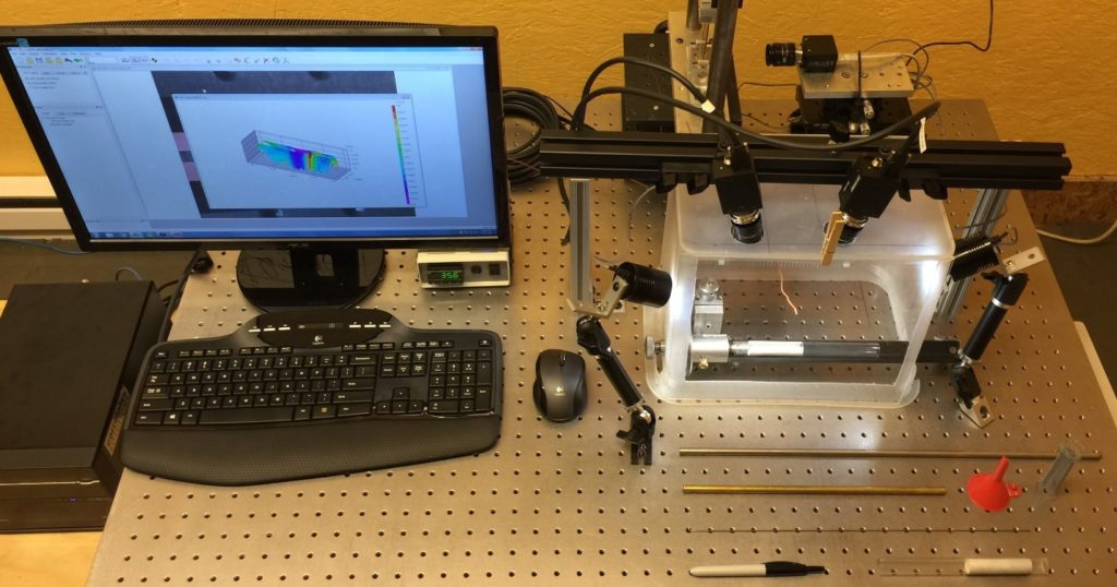
Figure 1. Experimental setup using the VIC-3D system

Dr. Perry began his experiments using perfectly straight silicone tubes that were custom made to have mechanical properties similar to a blood vessel. His experimental setup is shown above in Figure 1. The experiment involved deploying the stents into the tubes and measuring the resulting deformation. Dr. Perry knew that any simplified point or line measurement on his samples would have been misleading. This is where the VIC-3D system enters the experiment and provided Dr. Perry with the full field data he needed to be confident in his measurements and publish accurate results for his client.

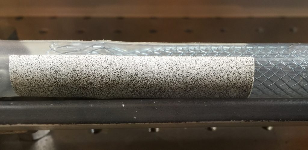
Figure 2. Speckled silicone tube with stent inserted.

The silicone tube was prepared for the experiment by having a speckle pattern applied by using off the shelf spray paint. The area of interest was masked off and a white base coat applied. The black speckles were then simply added by using an over spray technique with black spray paint. Figure 2 above shows the speckled silicone tube with the stent inserted.

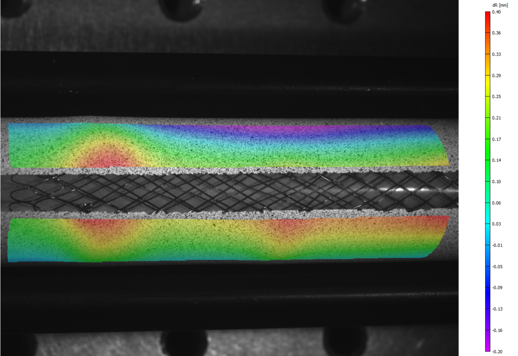
Figure 3. Change in radius contour under load from expanded stent.

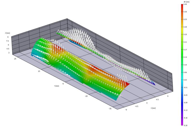
The change in radius variable and resulting contour plot was the most valuable data for Dr. Perry because it clearly shows the largest force is located near the end of the stent. This contour plot, shown above in Figure 3, also indicates areas of larger radial force that could have gone unnoticed using traditional measurement techniques.

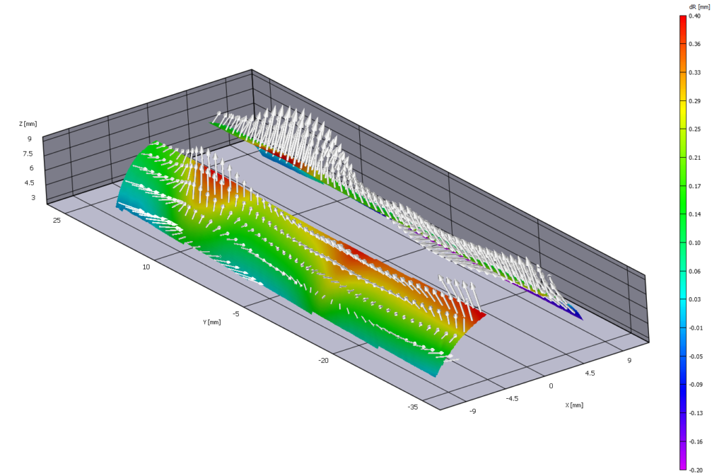
Figure 4. 3D change in radius contour plot showing displacement vectors.

Not only did Dr. Perry obtain full-field displacement data, he was also able to easily quantify the radial force profile of the stent and show the circumferential variation that resulted from the underlying woven stent structure.  Figure 4 above shows the displacement vectors of the stent in a full-field 3D contour plot. The displacement vectors show the magnitude of the resulting deformation which allows Dr. Perry to easily interpret the data as well as publish professional results for his client. The VIC-3D system gave Dr. Perry the ability to measure with confidence.

Testimonial

“Vic-3D was an amazing tool. Any simplified line or point-wise measurement would have been misleading. Vic-3D gave us full-field data we needed to be confident with the measurements.” -Dr. Kenneth Perry, ECHOBIO LLC

“We needed robust calibration, documentation and high-fidelity measurements so we designed our experiment accordingly using the VIC-3D system.”

More on VIC-3D

Thermal Imaging at Incredible Detail

By Comments Off on Thermal Imaging at Incredible Detail

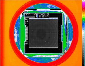
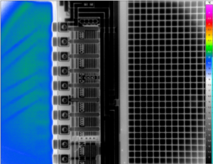
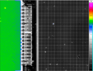
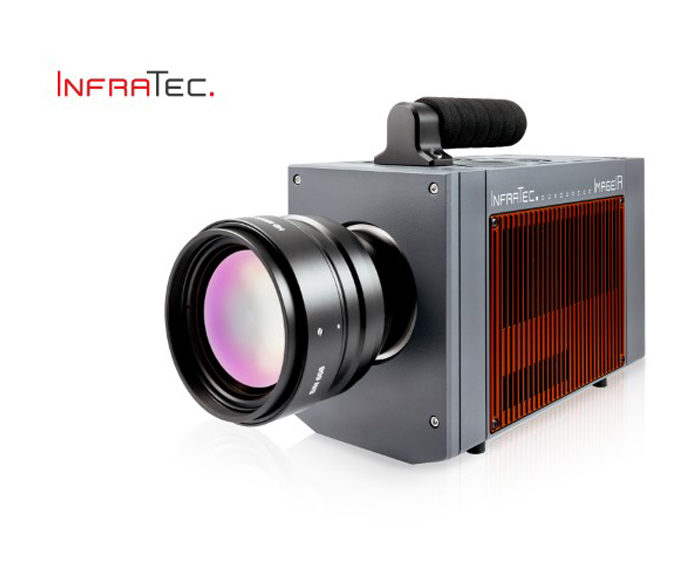
We recently had a look at an old iPhone 6 using Infratec’s ImageIR 9400, one of the most versatile IR cameras on the market. The spatial resolution of these cameras mean that the experiment was able to measure down to 1.25µm/pixel.


View ImageIR

Back Illumination High Speed Imaging

By Comments Off on Back Illumination High Speed Imaging

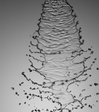
Back illuminated imaging is a widely used imaging technique. Under the correct conditions it can provide high contrast images of object’s. This is particularly important if you are interested in an objects’ shape or size.

The idea is a simple one – a light is shone towards the camera creating a white image, the subject is then passed between the light source and the camera thus blocking the light path and creating a dark area on the image. If the subject is stationary you can focus your camera onto the objects’ profile and obtain a sharp outline. If the subject is moving, in order to freeze the motion (remove blur) and obtain a crisp outline you will need to have a sufficiently fast shutter (short exposure time).

In extreme cases a strobe light source such as a pulsed laser or LED can be used. (For more detail on lasers please see our laser range.) Using this technique you will not be able to obtain 3D information about the object shape. If you wish to resolve features on the object surface you can use a combination of front and back lighting. The technique is not limited to solids, it can equally be applied to fluids, multi-phase flows, in fact any subject that will completely or partially block the path of light to the imaging sensor.

Optical Set up: The best results are obtained with a diffuse light source. This can be achieved by passing the light through a light diffusing medium such as a ground glass or opal diffuser plate, alternatively as a low cost solution opaque drawing film works very well. Where it is not possible to position the light behind the subject you can reflect it back to the camera using a white background

Uses

  • 1.  Spray analysis
  • 2.  Droplet impaction / coalescence
  • 3.  Particle size and shape
  • 4.  Bubble formation and growth
  • 5.  Ballistics
  • 6.  Welding

Analysis of Thermal Conductivity

By Comments Off on Analysis of Thermal Conductivity

Lock-in Thermography with Infrared Camera VarioCAM® HD research 800 (exact model not available in Australia)

New materials with precisely controlled optical and thermal transport characteristics can make a large contribution to resource-saving thermal management. Scientists of the University of Bayreuth are pursuing this vision. They use infrared thermography to quantitatively determine thermal conductivity in nano- and mesostructured polymer materials.

Thermal conduction and thermal radiation are essential transport mechanisms that play a key role in various applications, from the smallest microchips to complete buildings. Their control requires a sophisticated material design that reaches into the nanometre range. Prof. Markus Retsch and his team from the Chair for Physical Chemistry 1 of the University of Bayreuth are working on the development and characterisation of such innovative materials. Modern cooling and air conditioning systems still require an external energy supply. But the cooling technology of the future should work without additional energy. To achieve this, materials are needed that selectively radiate heat. This can take place, for example, in clear weather when radiation occurs into very cold outer space through the so-called “Sky Window” in the long-wave spectral range of 8 … 13 µm, in which the atmosphere is transparent. “This process is called passive cooling,” explains Prof. Retsch, “and requires materials that emit heat via thermal radiation within a selective spectral range. At the same time as little solar energy as possible should be absorbed from the sun, for instance by improving the reflection or scattering properties of the material.”

Thin Samples Actively Excited by a Laser

On the path to such passive cooling materials, understanding of the thermal conductivity process is important. To do this, Prof. Retsch’s group is working with free-standing samples of, for example, thin polymer foils, 3D-prints, and fibre mats with a film thickness of only a few hundred micrometres. These samples are investigated with the goal of determining their direction-dependent thermal diffusivity. With this value and including the specific heat capacity and density of the sample, the corresponding thermal conductivity is calculated.

As part of the analysis, the measurement objects are excited by an intensity-modulated laser. Depending on the characteristics of the sample, the heat flux extends differently into the material (see fig. 1). The scientists actively control the entire measurement through the thermography software IRBIS® 3. The infrared camera that they use, VarioCAM® HD research 800 from InfraTec, detects the emitted infrared radiation, whose intensity varies with the lock-in modulation frequency.